From high performance computing data centers and AI applications to ultra-compact electric vehicle (EV) batteries, the demand for next-generation power conversion technologies is relentless.
Chip fabs are in the race to deliver the latest node using wide bandgap semiconductors like Silicon Carbide (SiC) and Gallium Nitride(GaN) for higher output, faster speed, and less energy consumption.
The results are some extremely hot chips, from a temperature standpoint.
If you want to increase revenue this year by:
- improving quality in both chip and system
- shortening time-to-market
- reducing scrap
- lowering production and testing costs
Make thermal management a top priority!
TEST your thermal data, DON’T GUESS
Choosing the right metallized substrates to efficiently manage and dissipate heat generated during use is crucial to the overall performance and reliability of advanced power modules.
We take a look at a new ISO thermal characteristics assessment method for metallized substrates and power modules in mounted form.
Incorporating accurate thermal data of metallized substrates, particularly thermal resistance under real operating conditions, is essential for effective thermal budgeting.
This ensures that your design is both robust and reliable.
Fast & accurate substrate thermal evaluation
Thermal resistance under real workload
Thermal resistance is a property that measures the resistance to heat flow from a hotter area to a cooler area within a structure. It is quantified by the temperature difference across the material's thickness per unit of heat energy that flows through it per unit time. The standard unit for thermal resistance is Kelvin per Watt (K/W).
This data is essential for designing power modules that effectively manage heat.
Manufacturers of ceramic and metallized ceramic components can apply these standards to actively assess and optimize the heat dissipation properties of their products in typical operational scenarios.

Accurate thermal resistance data for thermal budgeting right from the start of the design.
Evaluating metallized substrates
Assessment Process: A TEG chip (SiC micro heater chip) heats one surface of the substrate sample, while the opposite surface is cooled using a heat sink. The temperature difference between the two surfaces and the power input for TEG chip (SiC micro heater chip) are used to calculate the thermal resistance.
Thermal assessment illustrated:
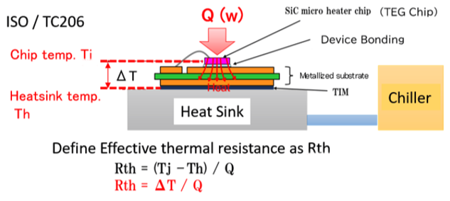
The ISO 4825-1:2023 thermal assessment for metallized substrate in mounted form.
This assessment protocol simulates the actual operating conditions of an advanced power module with the following specifications:
- This test is designed to evaluate the thermal characteristics of metallized substrate sample – components in which metallic circuit layers are joined to a ceramic substrate.
- A TEG chip (SiC micro heater chip), capable of generating at least 200W of thermal energy, is attached to the substrate sample to simulate an advanced power module. This TEG chip is made of silicon carbide (SiC) and has a thermal resistance of more than 250°C. Platinum thin films are bonded to the TEG chip to measure temperature during thermal assessment.
- Since ceramic has a lower maximum use temperature when placed under a compressive load compared to when it is not, a 10kg weight is placed on top of the metallized substrate during measurement. This is to mimic the actual operating condition of a metallized substrate in practical applications.
- A predetermined quantity and type of Thermal Interface Material (TIM) is used to fill the small gaps and irregular surfaces between components, enabling efficient heat transfer from a device to a heat-dissipating component.
- A water-cooled chiller is connected to the heat sink to provide constant temperature during measurement.
- Thermocouple type K, specified in IEC 60584-1, is used to measure temperature on the heat sink and is as thin as possible.
- A stabilized DC power source is used to supply electrical power for heating the heater chip is.
- A controller turns on or off the electrical power for heating.
- A recorder to simultaneously record the electrical power that heats the heater chip, the heater chip temperature, and the heat sink temperature and electric power.
Select the best suited substrate material to improve heat management and dissipation.
Find out how thermal properties in substrate materials affects to your application.
Discover how the TE100 Method can transform your operations
We're eager to demonstrate how the TE100 thermal characteristics evaluation analysis equipment can streamline your processes and significantly boost your revenue. Spending just half an hour with us could revolutionize how you manage thermal challenges in your designs.
Click here to download a comprehensive guide on substrate material thermal evaluation.
Email us at [email protected] or call us on 1-800-292-6286 to discuss your application with our engineering team.